Friday, August 26, 2011

Glass Heated Build Platform

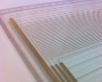
I finally got the prototype made. It came out really well and even though I have no idea how well it will work yet, visually I think it's great. I have some video of the writing process, but it took almost 30 minutes, so I need to do a bit of editing before I post it. Here are two shots of it right after writing the conductors and before baking:

Just after writing heater element
Both heater and thermistor elements
The first picture shows just the essential part, the heating element. It's about 2.2 Ohms overall so at 12 Volts that should use 5.5 Amps and dissipate 65 Watts. I think that will be enough for the 4"X5" piece of glass. The extra lines you see in the picture are actually just scratches in the X-Y stage.

The next picture shows the completed pattern which includes a very long thin looping conductor which ideally will work as a thermistor using the natural TCR (temperature coefficient of resistance) of the conductor. The higher the resistance, the better range I should get as a function of temperature, hence the need for long and thin. The resistance of the thermistor came out in the neighborhood of 230 Ohms. Once I can fire up and control the heater, I'll have to generate a lookup table to use in my firmware for bed temperature control.

After writing the conductors, the plate was fired for 3 hours at 850°C. Then I was able to solder wires to the conductor pads. I'd like to think of a better interconnect for the next version, but for the prototype, this will be fine.

Now I need to make myself a decent power supply out of one of the old ATX PC supplies I have lying around.

Unfortunately, this past week has not been all good for me on the 3D printing front. I was having a little trouble with backlash, mainly on the X-axis, and in the process of tightening the belt managed to pull off both of the bushing holders on the motor end, and two of the bushing holders from the X-carriage.
Bushing holder separation on X-axis

This is apparently a problem for more than a few people. I believe the belt went slack over time due to the motor mount being designed with a bit too little plastic. Eventually the belt tension pulled the pulley in enough to cause slack. I guess I got a little ham-handed trying to take up the slack and you can see some of the results. The cable tie I had on there was not enough to prevent the detachment of the bushings. Maybe it's me, but I think the desire to reduce the amount of plastic in the printer parts has gone a bit too far. I'm also at a loss to understand why the channel in the X-motor end and X-idler end faces away from the source of tension. I have a hard time believing there isn't a good reason for this orientation, but I'm damned if I can figure it out. I'm really impressed by the work I see on vertically oriented X-axis parts by Emmanuel and the Russians and I would like to do something similar once I get up and running again.

My goal with building the printer was to make parts for other projects, but I'm getting totally sucked in to the idea of improving the design.

Tuesday, August 23, 2011

The Best Laid Plans...

So much for the plan. Life events have made it a bit of a challenge to coordinate my schedule with that of the production team at work. So other than finding a time that I can actually make the test version of the glass HBP, I'm all ready to go. Here's a piece of the pattern that I'll be using for the first attempt (click to see it full size):

The lines represent the path that the Micropen will travel to lay down the conductor. The red path will be the heating element made with an overlapping 20mil line for a final line width of about 2mm. The blue trace will be a thermistor which will not overlap and be only 10mils wide and 550 inches long. I'll have to come up with a custom thermister table once I can test it out. I'm hopeful I'll actually be able to do this tomorrow or the next day.

Sadly, I haven't had much time for printing things lately. I managed to make half of the corners and the pins for a screwless cube gear, but the center is proving difficult for me to print in PLA as it's so small at the bottom that it's not cooling off quickly enough. I'm going to try printing it along with something else to see if that helps since I don't yet have a cooling fan on my x-carriage.

Wednesday, August 3, 2011

Plan for Glass Heated Build Platform

Example heater and thermistor on glass
I've read many success stories of using glass on top of a heated build platform, and some struggles as well. Seems that if you can get the plastic to stick throughout the print, removal after cool down is easy. So I've decided to use glass as the top surface, but rather than go the traditional route and just lay it on top of the heater, I'm opting to actually create the heater on the glass surface. I've mentioned previously that the company I work for makes resistors (including heaters and thermistors) on all sorts of substrate materials and shapes including glass vessels. The electrical elements are made by Micropenning the conductive ink onto the surface then baking.  So making a heater and thermistor on a flat square of glass should be easy.

The point of doing it this way for me is to ensure that the glass is very evenly heated since I won't have to worry about even contact with the surface beneath, and possibly to reduce the power requirements for the platform. Oh, and just because I can. I plan to create a test piece this coming week to check the uniformity of the heat distribution on the glass with my heater pattern, as well as to confirm my math on the electrical properties of the heating circuit. I'm not an electrical engineer, and I'm trying not to bother the experts at work too much (though they may say otherwise). I have a couple of nice pieces of scrap borosilicate glass to use from one of our previous projects. I may try standard tempered glass later if it proves out and I decide to make a few more.

RevK's 11&39 Wade's Gears
I tweaked my skeinforge settings a little more and printed out these fantastic gears by RevK. They really do print out very easily and they came out way better than I expected at this point. I think they'll go great on the Greg's Hinged Accessible Extruder I plan on printing once I can do ABS on my new HBP.