Friday, June 17, 2011

Test Cube and Other Stuff

I merrily played with the manual controls in RepSnapper and calibrated as well as I could with my primitive ruler in terms of making sure the three movement axes roughly followed my commands. I think my timing was good relative to the releases of Skeinforge as others who are much more experienced than I already figured out how to adjust the firmware to handle SF40's new volumetric extruder control. So I followed the empirical method in one of the forums for figuring out how many steps it took on the extruder motor to feed one mm of filament into the extruder and plugged that into the firmware. That gave me some confidence that the extruder was working properly too.

I have to say I was somewhat concerned that the PEEK insulator on the MakerGear hot end I was using would get hot enough to melt or at least warp the extruder plastic or X carriage. I brought a nice calibrated thermometer home from work and was really pleased to find that the temperature of the PEEK seemed to be staying below 80°C without any kind of active cooling. I can't say enough about how happy I am with this hot end setup.

As much as I would have liked to jump right in and print a replacement gear for the really warped large one my extruder, I still needed to calibrate, and I'd probably need a heated bed so I could print with ABS. I don't think the PLA would hold in that situation.

First print
So I looked for a tried and true standard on thingiverse and found the 40mm test cube. I found some settings to use as a starting point in Skeinforge (I haven't the faintest idea where any more) and ran the thing through. I really didn't understand what most of the parameters meant, but I got greedy and decided to shoot for a 0.2mm layer height. Out popped the G code which I then fed to RepSnapper. I noticed that the object appeared to be centered at 0,0 on the preview grid, but since the starting point was also 0,0 I figured the printer would just end up being forced to adjust and the cube would print with a 20mm shift away from the origin. I think I forgot to carry the 1 or something ;) I ended up with the lovely thing you see to the right.

It tried to print each layer shifted 40mm in the positive Y direction. Not surprising I suppose. But it certainly seemed to be trying to do the right thing. So I cleaned up the mess and prepared for another go. Realizing that 40mm is pretty big, and not wanting to use that much plastic at this point, I ran the stl file through Skeinforge again but used the scale function to make it half as big. I also did a little searching and found out you can use the multiply function in Skeinforge to move the origin of the object, which I did. The next print almost worked, but the nozzle seemed to be dragging through the plastic and just making a mess. I stopped it after the second layer.

I was having a hard time figuring out how to deal with the ooze right before a print and I figured that was what was tripping me up. So using the same code, I tried again and just did my best to keep the nozzle clean before the actual print started. And the results were........ fantastic!

Printing my first thing!
First successful print - 20mm cube
 It was the best looking roughly 20mm cube of black plastic I had ever seen. Maybe my judgement was a little clouded by finally getting something approximating what I asked for after all that work Googling, and assembing, and testing, and Googling some more. (Just noticed Googling is not in the Blogger dictionary, or is it Chrome, hmmm).

Flushed with this success, I tried to do it again. No joy. Decided to pack it up for the day and try again tomorrow. The next day wasn't any better. I just couldn't get the PLA to stick. You may have noticed in the pictures, I was using Kapton tape on the bed. I thought maybe I had too much residual plastic on the nozzle and took the whole extruder off so I could clean it up properly. A coworker suggested I polish the nozzle so I did. Tried again and it still didn't work. I was getting really frustrated at this point.

I turned to the reprap channel on IRC for the first time and was advised that PLA doesn't stick so great to room temperature Kapton and that preheating it with a hair drier might do the trick. About the same time, I had a revelation that I hadn't cleaned the bed at all since applying the tape. So I used some alcohol to clean it up. I used the hair drier for good luck even though I don't think that had anything to do with my issue but sure enough, my next print stuck fine.

Misshapen baby octopus
Real progress
I really thought I had it licked at this point, and being bored with cubes already decided to go hunting for something more interesting on Thingiverse. That's when I discovered the Bucket O' Octopi. I was still being stingy with the plastic and left my scale settings at 50%. The result was less than overwhelming, even though it was recognizable. The double legs are because I bumped the print bed after the first layer.

Time to start learning what all those numbers mean in Skeinforge. But before doing that I decided to just take a stab at some parameters and try again. On the next G code export, I noticed some numbers fly by in the terminal window. I could have sworn it said the layer height was set to 0.1mm. Sure enough that is what it said. I double checked my layer height setting in SF and it said 0.2mm. Then it dawned on me that for some strange reason, scale affects the layer height, but not the width. While this is pretty clearly a mistake in the code, once aware of it, you can easily work around it. Rather than try for the half size octopus again, I decided to go for the adult size. And it worked! Well, mostly.

Somewhere near the top of the head, something happened. I couldn't see it very well not having a ring light and all. It looked to me like it might have been stretching the filament a little too much on the infill, and on a layer near the top it broke. The end of the strand pointed up and caused the subsequent layers to get a little messy in that area as the nozzle dragged through it. But again, I was very pleased anyway as it seemed like I was making real progress.

One other thing I realized after all this is that the first successful test cube I printed actually had a layer height of 0.1mm. I didn't think that was even possible.

As I was saying, now it's time to learn what all those Skeinforge parameters are for. But first, a beer.

Wednesday, June 1, 2011

Hardware Done, Time for Firmware and Software

So all this blogging about the hardware might lead you to think I was really patient about waiting until it was all finalized before loading up the brains with some code to make it actually move. Well, I may have left out a little bit. I loaded Tonokip's firmware once I had all three movement related axes ready and made sure they were moving using Repsnapper for manual control. I was floored that they not only moved, but in the proper directions. A big thanks to all the RepRappers who took the time to document various pieces of the puzzle.

While getting the extruder all put together, I did some more research on firmware and software on the RepRap site, various blogs, and by lurking on IRC for a while as well.  This is probably one of the hardest parts of the whole process. A thread in the forums had just spawned a new page on the wiki that was intended to list computer OS/printer electronics/firmware/host software combinations that were known to be working. I just rechecked and it appears this never really got off the ground. I'll add to it once I feel my combination is worthy. The best options for you depend on many things. The wiki has a decent rundown of the various tool chains that might work for you.

I was looking for firmware that worked easily with my RAMPS setup. Initially I looked at the Teacup firmware but found it too confusing for my first attempt. I found the Tonokip firmware much easier to understand and configure for my setup. I later changed to Klimentkip and will probably move further up the evolutionary ladder to sprinter in the near future. All I needed to do was copy the RAMPS config file, check the pins and end stop settings (I used mechanical end-stops), and uncomment the include statement for the correct thermistor table.

For host software I decided to use Repsnapper just for control and sending the G-code to my printer. From my research, I gathered that Skeinforge offered the most advanced options for G-code generation and also a proportionally steep learning curve. I decided not to try printing with Repsnapper directly fearing that I would just be disappointed with the results anyway. Probably an unfounded decision as I've since seen some pretty good results from other RepRappers. Skeinforge is really a bear to learn, but I'm making progress.

Nothing left to do but print stuff.

Saturday, May 28, 2011

Extruder Assembly

I was originally planning on designing and building my own extruder. The company I work for allows me some unique opportunities as they have done heated barrels for numerous other applications and this would be relatively easy in comparison. However, my impatience got the better of me.

I already had a set of plastic for a Wade's geared extruder, so all I needed was the hardware and a hot end. I wasn't thinking about this when I ordered all the hardware for the rest of the machine, but the BOM does not include hardware for the extruder as this is really a separate entity with a whole lot of options. Fortunately a Wade's extruder doesn't need a whole lot. The only unusual part is the hobbed bolt. I decided to buy one from an ebay seller since I didn't have an easy way to do the hobbing, and it was just so cheap I didn't feel it was worth the effort. Other than that, just need four long bolt, springs, and nuts (I went with wing nuts) to hold the idler block on, three more 608 bearings for the hobbed bolt and pinch wheel, screws for the stepper, and a bunch of washers for spacing the big gear and bolt properly. I just got most of this at a local hardware store. I really hate how they rip you off when you only need a handful of pieces.

Wooden mount for Wade's and GrooveMount
I did a bit of research before deciding what to do with the hot end. My goal was to do something that was easy to assemble and maintain and relatively short so as not to cut too much travel out of my Z axis.  I really liked the aluminum block heater with a resistor that I saw first I think on nophead's blog. Just seemed very compact and easy to put together. I was prepared to make the pieces myself when I discovered that Makergear was selling exactly what I wanted at what I thought was a very reasonable price. I really liked the look of their V3 Hybrid GrooveMount assembly as well. So I got those along with the wooden mounting plates for Wade's extruder, a 36mm barrel, and the 0.35mm Mini Bighead nozzle all from Makergear (mmmm, chocolate too).

Assembled hot end
It all went together very easily once I figure out how it was meant to be wired. All the PTFE sleeving kind of threw me off. Also the heating resistor was much bigger on one end than the other, so I had to do some graduated reaming to get it to fit in nicely. I didn't originally use anything to hold it in the block other than the set screw, but I've since noticed it seems to have shrunk a little with use and I'll probably add some UV curable high temp stuff we have at work to secure it more thoroughly.

Ready for software. I can see the light at the end of the tunnel! Is that a train whistle I hear?

Completed extruder, mounted and ready to go!

Monday, May 23, 2011

Electronics - In which the author learns to solder, properly

AAA wirewrap, who knew?
With the mechanical build in good shape, it was time to move on to the brains (mmmmm, brains). I bought all my electronics fully assembled as I've had very little experience soldering small circuits. I did however need to solder the header pins onto the stepper drivers. Many thanks to Shannon at work for patiently teaching me how to solder those parts correctly. I'm not ready for SMT components yet, but I feel fairly confident I can handle most through hole bits.

The actual install went pretty painlessly. After trying to come up with something clever and unnecessarily complicated to wire the Z axis motors together, I just used some small wire nuts to get the job done. One great thing I found was that the plastic binding from AAA TripTiks make great wire wrap. They're particularly flexible since the spine is very thin which makes them really well suited for the wire bundles that have to move with the X and Z axis. As you can see, I could use at least one more. Time to plan the next vacation, or at least pretend to.

Check out the copper heat sinks
I wanted to be able to mount my electronics boards in a way that they were fully protected, but still visible. I really love the look of those little copper heat sinks. So I designed an enclosure intended for clear sheet material, and coworker Brian bent it up for me out of lexan. There was just barely enough thread left on the bottom crossbar to let me attach it through the tab that's bent to match the angle on the smooth rod clamp by the fan. My soldering teacher then helped me find and mount the nylon standoffs for the boards, and I mounted and wired the 40mm fan I found in my stash. I'm very happy with the way it turned out. I think I'll even have enough room to mount the SD card reader when I get that far.

One thing that did trip me up for a bit was the pin config for the steppers. Looking at the plans for the RAMPS board, the color codes of various steppers (no two of which are alike), and the datasheets for my steppers, I could not for the life of me figure out for sure how it should be wired. Then I realized that since I had ordered both the motors and the board from Ultimachine, all I had to do was match the picture in their catalog. I still think there needs to be a way of noting in the RAMPS instructions which pins go to each coil on the stepper. No two color codes, letters, or number schemes are alike between manufacturers.

All that was left for me to be able to print my new companion cube (I wanted to make up for incinerating my last one) was to get the extruder assembled and fire up the software. Don't laugh, I really thought that was all I needed.

Friday, May 20, 2011

The Fun Begins - Build Time

This post is just meant to cover some of the unexpected issues that came up during my build. The visual instructions for the mechanical part of the project that are available on Gary Hodgson's site are fantastic. I swear it wasn't more than a week after I finished the mechanical build that he posted that guide. There were some really nice YouTube videos linked from the reprap.org site for the Prusa Mendel that I used but the links seem to have gone AWOL (or I'm looking in the wrong place). I'm sure a quick search would find them.

Notched fender washer
Building the triangles and the horizontal connecting rods went great. Then I jumped ahead and tried to mount the Y-motor (that's the one in the front on the bottom if you go the traditional route), and found that the left fender washer in front was in the way of the mounting hole for the stepper motor. I still can't figure out what I did differently that made this a problem for me. So I ended up disassembling that front rod, cutting out a notch in the fender washer and reassembling. Oh, and this was after getting everything I had done so far squared up and spaced evenly.

At this point I realized I should have gotten my bushings into their bushing holders and put them onto the Y-axis smooth rods. I reamed the bushing holders, inserted the bushings, and tested them on the smooth rods. I wasn't real happy with the less than super smooth movement, so a coworker threw the rods on a lathe and really polished them up. It made a huge difference.

Normal vs. nylock #6 nut
This is when I first noticed something completely missing from the vitamins list. For the top of the Z-axis smooth rods and the captive nuts in the X ends, there was no way the nylock nuts were going to fit. I don't know if my #6 nylock nuts or plastic parts are atypical, but I found some "normal" #6 nuts and used those. So I needed 12 non-nylock nuts (4 for top of Z smooth rods, 8 for X ends), and I used another 2 later to mount my extruder.

Captive nut in X-end idler
One thing I wasn't thrilled with here was that there only seemed to be 2 layers of plastic holding the nuts captive in the X ends. It didn't take much tightening on the bolts to cause the plastic to start to deform. So I just tightened them as much as I though I could get away with that wouldn't crack the plastic.

Next came my first experience with gluing the bushings. I didn't see any guidance as to what glue to use other than to go with a two-part epoxy. I chose the Loctite epoxy for plastics. I probably didn't use enough the first time because in trying to move the X-axis down to get the Z lead screws in, three of the bushings came off. I used a lot more epoxy the next time and it has held so far.

Nice Delrin coupler (thanks Gary!)
I had planned to use the printed couplers for the top of the Z lead screws temporarily until I could make up something better, but for some reason the hole to accept the threaded rod was way too big. Even clamped as far as it could go, there was still close to an 1/8" gap. Coworker to the rescue again. Gary whipped up a pair of couplers out of Delrin for me which have worked out great.

It wasn't until I got the Z lead screws mounted that I realized just how lousy the standard threaded rod I had was for this purpose. I didn't think there was any point in trying to straighten it as it would clearly have a serious impact on the quality of my prints. So I ended up ordering a couple of one foot pieces of stainless threaded rod and it was much better.

When it was time to run the Z lead screws through the nuts in the X ends, I found that the nice silicon-bronze nuts I had gotten were too small on the outside to fit snuggly in the hexagonal hole. Even though the Z-axis would only be going one way during a print, it didn't seem right to have the nuts loose in there. So I ended up using some zinc jam nuts that fit in there without any play.

Bottom view of build plates
One last particular of my mechanical construction: I opted to use G10 (a fiberglass-resin composite) for the bed surfaces. There were plenty of good sized scraps of it available at work. I planned on doing a heated bed at some point, but I thought this would make a great unheated surface as it's really smooth and won't wick away the heat from PLA as quickly as aluminum. You can see in the picture that I had the bottom plate open in the middle to try to keep the weight down. Gary (did I mention I owe him at least a case of his favorite beer?) cut out the bottom plate for me and milled some nice pockets for the bushing holders. I wrapped the belt around the sides of the plate in order to keep it from slipping.

Everything else on the mechanical side went just as expected. Well, until I got to the extruder anyway. But I didn't work on that until after some electronics work.

Wednesday, May 18, 2011

The Really Easy Part - Buying Stuff

I always say I hate shopping, but I guess it just depends what I'm shopping for. I had already decided I was going to build a Prusa Mendel and after seeing a number of posts claiming that SAE was easier to get hardware for than metric on this side of the pond, I searched ebay for a suitable set of printed parts. There weren't a whole lot of choices at the time, but this one particular seller seemed to know his stuff and the parts in the pictures looked really good. Fortunately for me, they were.


And even though they were pictured on rafts, they didn't arrive that way. In fact, they really needed only a little cleanup and removal of support material.

At the same time, I ordered the assembled RAMPS board from Ultimachine, an Arduino Mega from Makerbot (also assembled), and Pololu stepper drivers straight from the source. Stock seems to change on an almost daily basis at many places. I later ordered the five stepper motors from Ultimachine after doing some research. They seemed to be on the high end for torque but still a very reasonable price. I've since realized this particular motor is probably overkill for a Wade's extruder setup, but I haven't seen a downside. I couldn't find stepper drivers that included the heat sinks at the time, and couldn't find heat sinks that looked anything like the ones you normally see on the drivers. Finally, in some forum I found a reference to video card mosfet heat sinks as a potential solution which I was able to order from newegg.com. They're really tall, but I was confident they would do the job.

While the electronics were on their way, I raided the hardware drawers at work for nuts, bolts, and washers. They had almost enough of everything I needed, and I didn't even have to steal them. I ordered the threaded and smooth rods, belt, bronze bushings, and nylock nuts per the vitamins list on reprap.org. If you get plastic parts with fully printed bushings you won't need the bronze ones. I went with bronze for durability.

I was planning on getting opto endstops when they became available somewhere, but a coworker gave me 3 really nice magnetic reed switches from Parker Automation. While I was trying to think of a clever way to mount them and the magnets, I remembered that I had some mechanical switches in my pile of junk that I save for just such occasions. Found three small ones that work great.

That concluded the big shopping spree. Turns out it can be enjoyable. Then it was down to the waiting. Definitely my least favorite part.

Monday, May 16, 2011

End of the Beginning

I never really expected to be writing a blog, but since that's where I found a lot of useful information on the web, I think this might serve to help other first timers who find the whole process intimidating, and the hunt for information as challenging as I did. It's really kind of a scavenger hunt.

My motivation was to be able to create parts for other robotics, automation, and artistic projects. This seemed like a much easier route than getting a hobbyist's machine shop together. I also wanted to give my kids a tool to allow them to create any sort of thing they can dream up. They are very good at thinking of things I would never have thought of. I thought it was amazing when I first told my 10 year old what a 3D printer was and his first question was "could you use it to make more 3D printers?" I hadn't even told him that was one of the prime directives of the RepRap project.

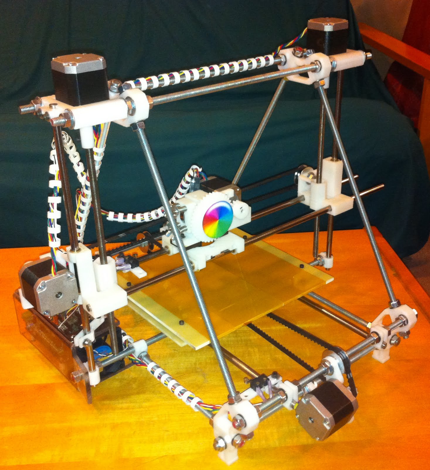
Anyway, I've finally finished the actual build of my first RepRap, at least as much as a RepRap build can ever be called "finished". There are a number of improvements I'm already planning, but it's at least at a state where I can begin to try to print things. Ta-Da!

It's fairly typical in many ways. Based on the guidance I was able to glean from many forum posts, blogs, and other online sources, I went with the Mendel Prusa design, with RAMPS electronics from Ultimachine, and a Makergear hot end using their experimental HeatCore V2 which I believe is based on nophead's design.

I'll work back a little in my following posts to explain some of the minor snags I ran into during the build.